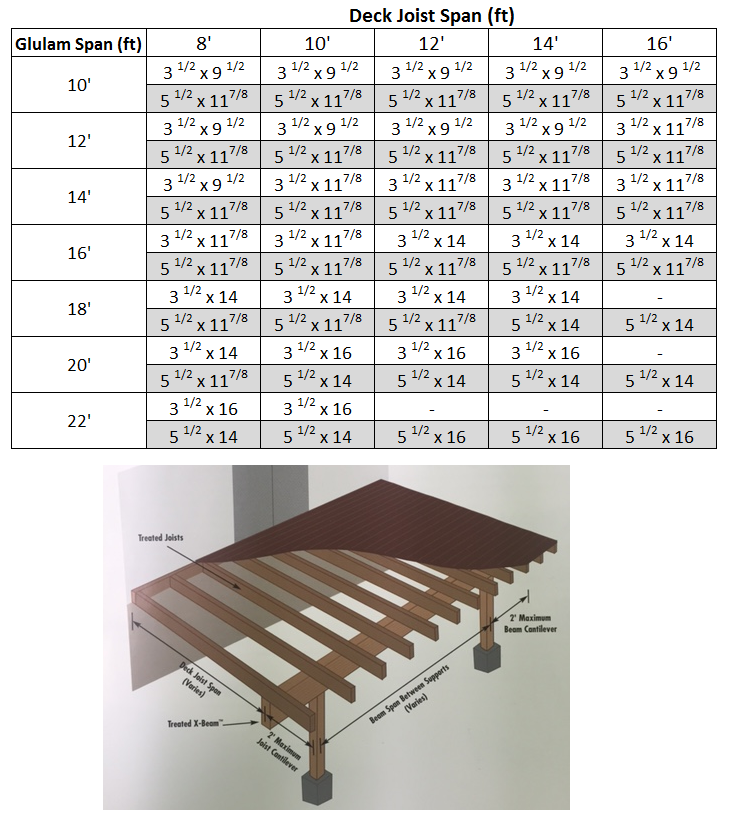
Glulam Beam Span Chart
Glulam Beam Span Chart - • table values for minimum required bearing lengths are based on the allowable compression design value perpendicular to grain for the beam and the load value Full lateral support on the compression side. Web tables 2, 3, 8 and 9 provide allowable loads for glulam beams used as simple span roof members for non‑snow loads (dol factor = 1.25) and in snow load areas (dol factor = 1.15). Its overall length is therefore 1.2l, and the suspended beam’s length is 0.8l. As per thumb rule & general guideline, depth of the glulam beam is 1/20th of span in inches and their width is 1/3 to 1/4 of the depth. Web tabulated total load (tl) is based on the deflection criterion of span/180. Total load deflection limit = span/240. Web section properties and capacities and allowable loads for simple span glulam beams Web tables 2, 3, 8 and 9 provide allowable loads for glulam beams used as simple span roof members for non‑snow loads (dol factor = 1.25) and in snow load areas (dol factor = 1.15). • table values assume that lateral support is provided at each support and continuously along the compression edge of the beam. Web tables 2, 3, 8 and 9 provide allowable loads for glulam beams used as simple span roof members for non‑snow loads (dol factor = 1.25) and in snow load areas (dol factor = 1.15). • table values for minimum required bearing lengths are based on the allowable compression design value perpendicular to grain for the beam and the load value Tabulated total load (tl) is in addition to beam weight (assumed 35 pcf). Note, interpolation of the maximum span between adjacent rafter spacing’s or loaded width’s is permissible. Total load deflection limit = span/240. As per thumb rule & general guideline, depth of the glulam beam is 1/20th of span in inches and their width is 1/3 to 1/4 of the depth. Web tabulated total load (tl) is based on the deflection criterion of span/180. Live load ≤ 0.67 x total load. Web glulam beam size calculator. Web see figure 2 for details of the following cantilever systems: Web the span tables for the rafters, ridge beams, roof lintels and floor lintels are given in appendix b, c, d and e respectively. Full lateral support on the compression side. Web tables 2, 3, 8 and 9 provide allowable loads for glulam beams used as simple span roof members for non‑snow loads (dol factor = 1.25) and in snow. As per thumb rule & general guideline, depth of the glulam beam is 1/20th of span in inches and their width is 1/3 to 1/4 of the depth. Full lateral support on the compression side. Note, interpolation of the maximum span between adjacent rafter spacing’s or loaded width’s is permissible. Rule of thumb for sizing glulam beam: Web the span. Web tables 2, 3, 8 and 9 provide allowable loads for glulam beams used as simple span roof members for non‑snow loads (dol factor = 1.25) and in snow load areas (dol factor = 1.15). Its overall length is therefore 1.2l, and the suspended beam’s length is 0.8l. Web see figure 2 for details of the following cantilever systems: •. Web section properties and capacities and allowable loads for simple span glulam beams • table values assume that lateral support is provided at each support and continuously along the compression edge of the beam. Selected beam size shall satisfy both live load and total load. Full lateral support on the compression side. Web glulam beam size calculator. Tabulated total load (tl) is in addition to beam weight (assumed 35 pcf). Web tables 2, 3, 8 and 9 provide allowable loads for glulam beams used as simple span roof members for non‑snow loads (dol factor = 1.25) and in snow load areas (dol factor = 1.15). Web the span tables for the rafters, ridge beams, roof lintels and. Note, interpolation of the maximum span between adjacent rafter spacing’s or loaded width’s is permissible. • table values assume that lateral support is provided at each support and continuously along the compression edge of the beam. Full lateral support on the compression side. Web the span tables for the rafters, ridge beams, roof lintels and floor lintels are given in. Its overall length is therefore 1.2l, and the suspended beam’s length is 0.8l. Rule of thumb for sizing glulam beam: • table values for minimum required bearing lengths are based on the allowable compression design value perpendicular to grain for the beam and the load value Tabulated total load (tl) is in addition to beam weight (assumed 35 pcf). Web. As per thumb rule & general guideline, depth of the glulam beam is 1/20th of span in inches and their width is 1/3 to 1/4 of the depth. Rule of thumb for sizing glulam beam: • table values for minimum required bearing lengths are based on the allowable compression design value perpendicular to grain for the beam and the load. Web tabulated total load (tl) is based on the deflection criterion of span/180. Web section properties and capacities and allowable loads for simple span glulam beams Live load ≤ 0.67 x total load. Its overall length is therefore 1.2l, and the suspended beam’s length is 0.8l. • table values for minimum required bearing lengths are based on the allowable compression. Web • span is measured center to center of the supports. Web tables 2, 3, 8 and 9 provide allowable loads for glulam beams used as simple span roof members for non‑snow loads (dol factor = 1.25) and in snow load areas (dol factor = 1.15). Web see figure 2 for details of the following cantilever systems: Web the span. As per thumb rule & general guideline, depth of the glulam beam is 1/20th of span in inches and their width is 1/3 to 1/4 of the depth. Its overall length is therefore 1.2l, and the suspended beam’s length is 0.8l. Selected beam size shall satisfy both live load and total load. Web see figure 2 for details of the following cantilever systems: • table values assume that lateral support is provided at each support and continuously along the compression edge of the beam. Web tabulated total load (tl) is based on the deflection criterion of span/180. Tabulated total load (tl) is in addition to beam weight (assumed 35 pcf). Web • span is measured center to center of the supports. Live load ≤ 0.67 x total load. Full lateral support on the compression side. Web the span tables for the rafters, ridge beams, roof lintels and floor lintels are given in appendix b, c, d and e respectively. Rule of thumb for sizing glulam beam: Total load deflection limit = span/240. Note, interpolation of the maximum span between adjacent rafter spacing’s or loaded width’s is permissible. Web tables 2, 3, 8 and 9 provide allowable loads for glulam beams used as simple span roof members for non‑snow loads (dol factor = 1.25) and in snow load areas (dol factor = 1.15).
Birleştirmek Mücadele etmek kısaltın glulam span tables
Laminated Wood Beams Span Tables

Lvl Beam Span Tables Pergola

Glulam Beam Weight Chart Printable Templates Free
Birleştirmek Mücadele etmek kısaltın glulam span tables
Laminated Beam Chart The Best Picture Of Beam
Span Glulam Beam Sizes Chart

Glulam Span Chart For Beams
Glulam Beams
Glulam Beam Header Span Table Elcho Table
Web Tables 2, 3, 8 And 9 Provide Allowable Loads For Glulam Beams Used As Simple Span Roof Members For Non‑Snow Loads (Dol Factor = 1.25) And In Snow Load Areas (Dol Factor = 1.15).
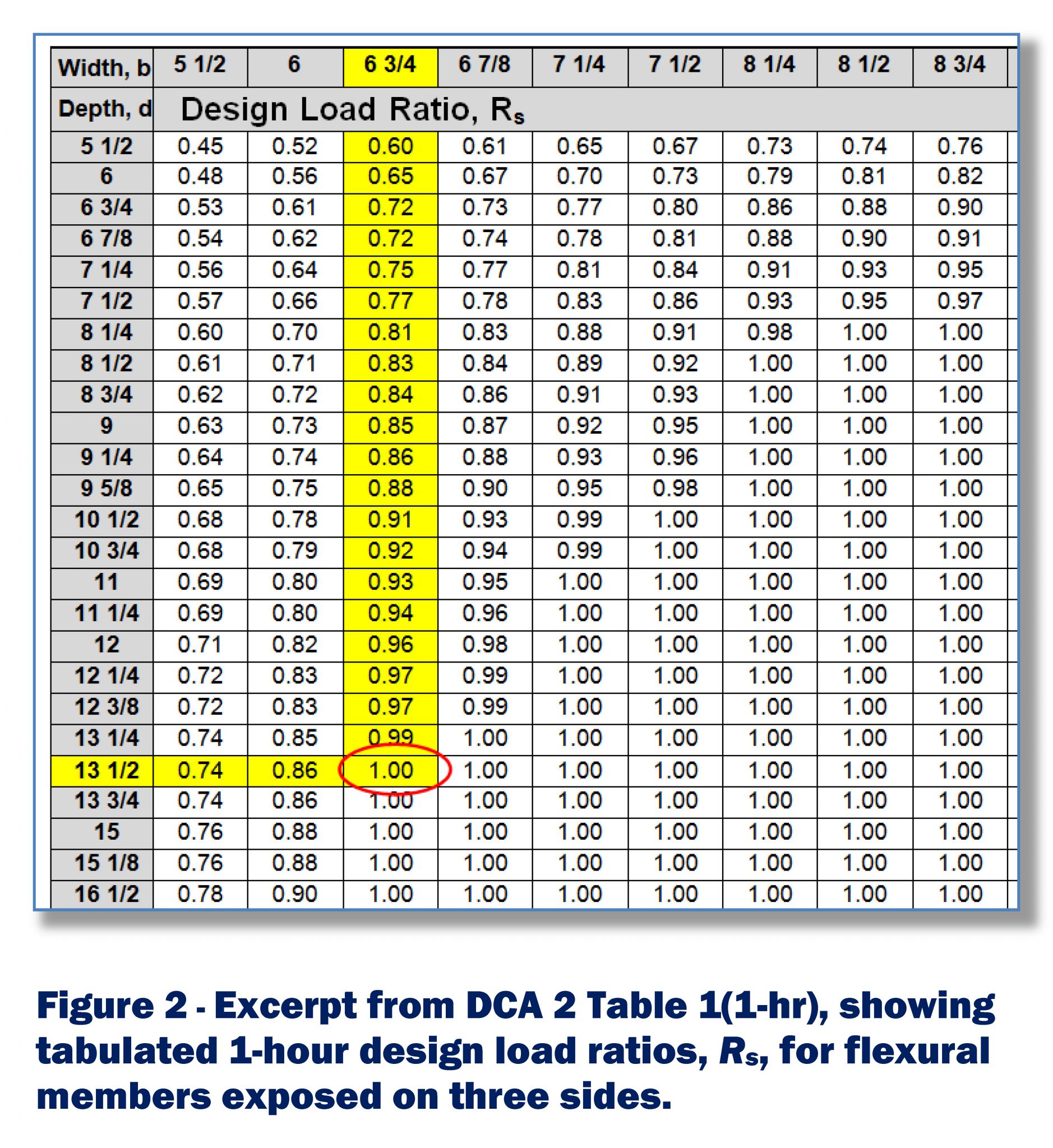
• Table Values For Minimum Required Bearing Lengths Are Based On The Allowable Compression Design Value Perpendicular To Grain For The Beam And The Load Value
Web Section Properties And Capacities And Allowable Loads For Simple Span Glulam Beams
Web Glulam Beam Size Calculator.
Related Post: